September 4, 2018
#272
Gentle reader,
There
is something very appealing about 1960's through 1970's home stereo
receivers. Wood (or very good vinyl) veneer covers, shining aluminum
faceplates, those broad analog tuning dials with various meters. Plus
all those aluminum switches knobs and buttons. What's not to like?
I’ve had a number of them, but never a classic Fisher. I belong to a number of FaceBook classic/vintage audio groups. One member was gushing about his new Fisher RS-1035 receiver and it’s amazing tuner. Hmm, so on to eBay I went. I found one that works but had some minor issues. And, Sold!
Made from 1978 to 1982, this is one of a number of Fisher Studio Standard models. They came larger and more powerful and smaller and less. With the upping of the power output usually includes lots more buttons, switches and knobs.
Some from this era went crazy with all the doodads they added to the front faces. This one is rather modest.

I neglected to keep a "before" picture, so here is the seller's photograph.

See that nasty mark on the faceplate in front of the meter? And the jagged edge below it? Those were a challenge to repair, as you shall see.


 Very attractive and well made vinyl veneer, although I prefer the real thing. It has held up much better than the type Pioneer used back then.


This is the view of the rear after I have cleaned it up and added a 75 Ohm coaxial FM cable to it.
See those cheap spring terminals on the right end? They are no longer in place. I hate those things and since it is a low powered unit (35 watts-per-channel), they only allow about 18 gauge wires.
WARNING: I have more than forty years experience working with electricity and take all precautions to protect myself. The safety warning labels on electronics should be heeded! Do not attempt to open anything that uses electricity unless you KNOW what you are doing.
WARNING: I have more than forty years experience working with electricity and take all precautions to protect myself. The safety warning labels on electronics should be heeded! Do not attempt to open anything that uses electricity unless you KNOW what you are doing.
Aside from that, I knew the signal strength meter did not work, but another seller had the exact one I needed and it worked for a bargain price.
Now, let's take a look under the hood. Since Fisher started making components well back in the time when everything used vacuum tubes, they continued the tradition of bisecting the unit horizontally and having a number of parts hidden beneath that middle floor, so to speak.

Above is the view from the front looking under the "middle floor"
The receiver has steel construction encased in wood. Top and both sides are one piece, plus a wooden bottom cover which the rubber feet are attached to. It is painted flat black. Removing the screws that hold it on and you are treated with the views seen above and below.
Below is a view from the rear looking towards the front.


Above is the components attached to the front wall behind the faceplate.

I readily admit I do not know what each board is for, but some I do. Above is a power supply board. The black square object is a bridge rectifier. It used four diodes arranged in such a way as to convert AC or Alternating Current to DC or Direct Current.

I haven't a clue what this one does.

Bottom of power capacitor, above.

Above, left to right, is the on/off switch, then the headphones plug and the speaker/phones selector switch.

Bass, Treble and Balance controls are these three, above.

These are the various button switches and the volume control.

Source switch is multi-layered and the secondary Record Out receptacle which uses the same type of 1/4" phone plug as headphones do. Called a "phone plug" because it's first use was for telephone switchboard operators.

Above shows the insides beneath the wooden/veneered cover. I have begun removing the dead signal strength meter, top right corner. I've always been fascinated by analog radio tuners. The pulleys all over the place with carefully strung string to move the needle on the front past the dial numbers. And the "front end" that includes the tuner which uses two devices comprising many fins that rotate, one moves, the other is fixed. Somehow, that finds all the frequencies. It's on the left, below, with the black wheel wound with string.

As stated, above is the front end. All that you see is just for tuning the AM and FM frequencies and removing the multipath signals to separate the left and right channels for FM stereo. Pretty cool, huh?

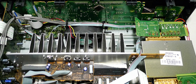
Prior to the making of this receiver, Sanyo of Japan bought Fisher. They carried on the Fisher tradition rather well. Shown here are their integrated circuits that replace two pairs of traditional power transistors.These get warm and thus they are attached to the black metal heat sink that takes up much of the back panel of the receiver.
 THIS is not from the inside of this Fisher, but a much newer Pioneer multi-channel receiver. See the gray object with white stuff on it below that small brown board? If you look closely, on the right side it has SANYO on it too. The white stuff is a thermal solution that makes contact with heat sinks better at transferring the heat. Just thought I'd show you this to point out that makers choose components from many sources, even their competition.
 Another look inside the top portion. The big black object is the power transformer. Easily the heaviest part of an amplifier. Black cylinder is a power capacitor which stores energy for the speakers. Usually there are two, but they somehow combined two capacitors within one cylinder.
 Above is a closer look at the old signal strength meter as I was removing it. The wiring for it goes underneath the middle floor.
 Above and below are two views of the wiring to the capacitor and then to the original speaker terminals.

Now that you have seen the insides, let me show you what I did to remedy those awful spring speaker terminals.
I gathered wires the same gauge and color as the original, made a sketch of what went where, as well as photographs, then cut the wires to the original terminals, then removed it from the back panel.
 A steel terminal box with an open bottom (so they can be stacked in service) was exactly what I needed. Fifty cents at a Habitat Restore store. Wonderful places to explore and shop within. Plus, it helps raise money for a wonderful organization that builds new house and GIVES them to needy families. former U.S. President Jimmy Carter (93) and his wife Rosalynn (90) still work on building houses. Awesome!
 I soldered them all together and uses heat shrink tubing to insulate the joints.
 To clear the fuse, I cut a notch in the bottom of the box. I secured the bottom with reusable adhesive. Wonderful stuff with a multitude of uses. To access the fuse, one simply unscrews the cover, pulls it out and there it is.
 The eight-terminal speaker plates usually come with identical connections on both sides. I came across these that are used in networks and they are perfect. The inside has a smaller hole which is what I needed.
 The wiring is protected by the extra layer of insulation from the tubing as it passes through the hole.
 If it had occurred to me beforehand, I would have used my strippers to clear an area about an inch and a half back from the end of the black wires. But I didn't so ended up soldering them together hoping they would fit through the holes, they did. I usually do not "tin" speaker wires or cables, but the small nuts easily cut the thin wiring when I tightened them. So, solder to the rescue to thicken and strengthen the wee wires.

 I could have had my wife make labels for these, but since it was four letters, a Sharpie did the trick.
 The Fisher can now accommodate any size cables that will fit through the new terminals as well as spade lugs and my favorite, Nakamichi banana plugs.
 Unlike newer receivers which usually have a threaded terminal for 75 Ohm coaxial cables, this one features a clamp to hold (and ground) the braided shielding beneath the black insulation and a terminal to clamp on to the central wire which carries the signals from the antenna.
 Only three inputs, which would never do for me in the listening room, but here in the "office", it is fine. I polished the outside of the RCA terminals with a green Scotchbrite pad. I blew the dust seen in the holes out with canned air. Which is "air" one should NEVER try and breathe!
 A close look will reveal the metal has been carefully sanded to remove the damage. See the working meter, above?
 All the knobs and buttons are solid aluminum, not like newer stuff which are painted to resemble the real thing.
 My idea to remove the rub marks from the clear plastic worked, however, despite wet sanding with up to 2000 grit sandpaper, there remained fine scratches on the plastic. Rats.
Fortunately, the same seller I bought the meter from also was selling a faceplate. I paid too much, but when one is holding the ONLY one for sale, they can set and get their price.
There are two layers of clear plastic. The outer one has the silver line across the top on the inside. It is backed by thin foam tape to prevent movement. Behind the tuning knob is a round plastic piece which the outer lens is screwed to. One has to remove all the knobs, and the nut on the function and speaker switches. There are four screws across the top that hold it in place. Once all that is out, it comes off easily. The front lens, I don't know what else to call the clear plastic, is further held by two bent copper pieces that hold each end of the top secure.
I had fun taking this all apart and fixing/modifying it. It looks as good as I could make it. I removed 30+ years of dust from inside as well as cleaning and lubricating all the many controls with Deoxit. Everything works now and all controls do their thing in silence.
Now, my thoughts: As you may recall, I have been using a Yamaha RX-496 black receiver here in my "office", which is MUCH newer than this Fisher and puts out more than twice the power. No signal meters or analog dials, all done electronically. The Fisher has a MUTING switch on it that silences the hiss between FM stations. This is good. The Yamaha simply finds and locks on to the station and you have clear stereo FM. I have found on the Fisher that the signal strength is often higher than where I am able to actually catch the stereo signal while tuning it. This is frustrating. No presets, nope, one must twirl that knob, (it does work smoothly, though) and carefully tune until the FM STEREO lights up. Manually tuning to a new station every time. Often, I end up using the MONO switch to get better sounding music. I also tend to have to use the HIGH FILTER or turn down the treble on the Fisher to get rid of the hiss. Yamaha wins the FM round.
 The Yamaha wins the inputs round too. That's it on top of the Pioneer which has the SANYO part in it I showed you earlier. This photo is from a previous article comparing modern Stereo receivers to Home Theater ones.
The Yamaha has the aforementioned terminal for the coaxial FM antenna cable as well. Sadly, no threaded, I had to buy an adapter to slip on to it.
Both have two AC receptacles, so that is a tie. One is switched and one unswitched on the Fisher. The manual gets it wrong, however, the unswitched should be used with a turntable, not the other way round as it posits. This is because you might switch off the receiver and the player slows down and stops with the stylus still in the groove.
THUMP. That is the sound my speakers make when I shut off the Fisher. Even if I turn down the volume. The only way to stop it is to switch off the speakers. No sounds when turning the Yamaha off or on. (I had a PROTON AI-3000 that did that when I turned it ON. No speaker switch on that, so I had to incorporate an attenuating volume control into the speaker cable circuit, rotating it all the way off before shutting that PROTON off and not rotating it all the way up until after the thump did it's thing.) So that is a negative for the Fisher too.
On looks, as mentioned at the very beginning. These vintage receivers just look "mahvelous", as one of Billy Crystal's characters used to say. Fisher wins the looks round.
Back to FM tuning, the Fisher captures distant FM stations that the Yamaha skips right past. Fisher wins the tuner sensitivity round.
The Fisher has a stepped volume control. I don't like that it's a little loud here, turn it down one click, now a little too quiet. But that's just me.
I have had sometimes to make sure the BASS tone control is not set too high with the Fisher. I have heard distortion or perhaps the woofers bottoming out (small inefficient speakers) sometimes. With efficient speakers such as my C-V LS12s or BOSE 301s, the Fisher shines. This never happens with the Yamaha, but I'll call this a non-issue because I may have been asking the SANYO SS1001 Power Amps in the Fisher to do more than they were designed to.
To conclude, this has been fun, I have spent more than the whole is worth on parts making it whole. But that is OK, one almost never recovers their expenses when fixing something up, like say a classic car.
Again, I love the looks, but I would want to get a silver cassette deck to match and perhaps a period turntable and a silver faced CD player as well. Plus, aside from right here, next to me, there is NO place in the house to use it.
So, for now, it is available on eBay for way less that I have into it. rfcollectin | eBay
Thank you once again for taking the time to read my (many) words and view my photographs. It is a labor of love and I really enjoy your feedback.
Scott
September 4, 2018
#272


Now that you have seen the insides, let me show you what I did to remedy those awful spring speaker terminals.
I gathered wires the same gauge and color as the original, made a sketch of what went where, as well as photographs, then cut the wires to the original terminals, then removed it from the back panel.


Fortunately, the same seller I bought the meter from also was selling a faceplate. I paid too much, but when one is holding the ONLY one for sale, they can set and get their price.
There are two layers of clear plastic. The outer one has the silver line across the top on the inside. It is backed by thin foam tape to prevent movement. Behind the tuning knob is a round plastic piece which the outer lens is screwed to. One has to remove all the knobs, and the nut on the function and speaker switches. There are four screws across the top that hold it in place. Once all that is out, it comes off easily. The front lens, I don't know what else to call the clear plastic, is further held by two bent copper pieces that hold each end of the top secure.
I had fun taking this all apart and fixing/modifying it. It looks as good as I could make it. I removed 30+ years of dust from inside as well as cleaning and lubricating all the many controls with Deoxit. Everything works now and all controls do their thing in silence.
Now, my thoughts: As you may recall, I have been using a Yamaha RX-496 black receiver here in my "office", which is MUCH newer than this Fisher and puts out more than twice the power. No signal meters or analog dials, all done electronically. The Fisher has a MUTING switch on it that silences the hiss between FM stations. This is good. The Yamaha simply finds and locks on to the station and you have clear stereo FM. I have found on the Fisher that the signal strength is often higher than where I am able to actually catch the stereo signal while tuning it. This is frustrating. No presets, nope, one must twirl that knob, (it does work smoothly, though) and carefully tune until the FM STEREO lights up. Manually tuning to a new station every time. Often, I end up using the MONO switch to get better sounding music. I also tend to have to use the HIGH FILTER or turn down the treble on the Fisher to get rid of the hiss. Yamaha wins the FM round.

The Yamaha has the aforementioned terminal for the coaxial FM antenna cable as well. Sadly, no threaded, I had to buy an adapter to slip on to it.
Both have two AC receptacles, so that is a tie. One is switched and one unswitched on the Fisher. The manual gets it wrong, however, the unswitched should be used with a turntable, not the other way round as it posits. This is because you might switch off the receiver and the player slows down and stops with the stylus still in the groove.
THUMP. That is the sound my speakers make when I shut off the Fisher. Even if I turn down the volume. The only way to stop it is to switch off the speakers. No sounds when turning the Yamaha off or on. (I had a PROTON AI-3000 that did that when I turned it ON. No speaker switch on that, so I had to incorporate an attenuating volume control into the speaker cable circuit, rotating it all the way off before shutting that PROTON off and not rotating it all the way up until after the thump did it's thing.) So that is a negative for the Fisher too.
On looks, as mentioned at the very beginning. These vintage receivers just look "mahvelous", as one of Billy Crystal's characters used to say. Fisher wins the looks round.
Back to FM tuning, the Fisher captures distant FM stations that the Yamaha skips right past. Fisher wins the tuner sensitivity round.
The Fisher has a stepped volume control. I don't like that it's a little loud here, turn it down one click, now a little too quiet. But that's just me.
I have had sometimes to make sure the BASS tone control is not set too high with the Fisher. I have heard distortion or perhaps the woofers bottoming out (small inefficient speakers) sometimes. With efficient speakers such as my C-V LS12s or BOSE 301s, the Fisher shines. This never happens with the Yamaha, but I'll call this a non-issue because I may have been asking the SANYO SS1001 Power Amps in the Fisher to do more than they were designed to.
To conclude, this has been fun, I have spent more than the whole is worth on parts making it whole. But that is OK, one almost never recovers their expenses when fixing something up, like say a classic car.
Again, I love the looks, but I would want to get a silver cassette deck to match and perhaps a period turntable and a silver faced CD player as well. Plus, aside from right here, next to me, there is NO place in the house to use it.
So, for now, it is available on eBay for way less that I have into it. rfcollectin | eBay
Thank you once again for taking the time to read my (many) words and view my photographs. It is a labor of love and I really enjoy your feedback.
Scott
September 4, 2018
#272


Very thorough. Thanks.
ReplyDeleteThanks. And thanks for reading it.
DeleteGreat stuff. Learned a lot just reading and looking.
ReplyDeleteThanks for reading my blog and commenting Dan.
DeleteI have a Proton 930 that has clips, too. May use your technique to get posts there.
ReplyDeleteI hope it works for you.
DeleteYo tengo un , y no lo e revisado aun, gracias por todos los datos.
ReplyDeleteDe nada.
ReplyDelete