October 23, 2018
#281
Gentle reader,
Do you drive two pairs of speakers at the same time? I do. Some say it degrades the sound, but I disagree. I believe the two pairs correct each others weaknesses and combined sound is an improvement.
Or, do you have an amplifier or receiver that thumps your speakers when you turn it on or off?
Or, do you have an amplifier or receiver that thumps your speakers when you turn it on or off?
Do you like to do A/B speaker comparisons? If so, it is vital to make sure each tested pair is putting out the same level (decibels) of sound. Otherwise, we tend to pick the louder pair as sounding better.
Or, are you listening to remote speakers powered by an amplifier in another room?
Well, a portable volume attenuator is your solution. I built this one and so can you.

I have always been handy, but I feel the average person should be able to copy or improve what I have done here. No soldering is involved.
I built this years ago when my stereo was in the living room and I had a pair of speakers in this room which is at the opposite end of the house. It sat right next to my desk chair in this room. Very handy if the phone rang, or my wife is standing in the doorway trying to get my attention.
There are two ways to
go about this. The way I built it, OR browse your local hardware store
and find an electrical box or two boxes that can be nested, that is/are able to have the two items needed to
be screwed into it. The control on the front and the speaker terminals on the back.
It is strongly recommended that you purchase a digital Volt-Ohm-Meter. They are very inexpensive, especially at Harbor Freight. It is invaluable in this project and you will be surprised how often you will use it in the future.
It is strongly recommended that you purchase a digital Volt-Ohm-Meter. They are very inexpensive, especially at Harbor Freight. It is invaluable in this project and you will be surprised how often you will use it in the future.

What I used is called a Two-Gang Box. That means you can install two switches, outlets or whatever side by side in one box. I chose a steel box since most of the plastic ones are blue or white and have all kinds of protuberances molded to them to allow for attachment to a 2X4 wall stud. Plus, they are not suited to what I wanted to achieve.
As you can see I attached a plate to the box that has four screw holes to attach the volume control and speaker terminal plates to.

See how the screw holes are the same distance apart (top to bottom) on both pieces? You can buy a two-piece speaker terminal plate if you want. I tried one, but it seemed unstable. It was too thick and the volume control's surface did not line up with the terminal's face plate. So, it was a one piece terminals for me.

Regardless of which style you choose, you are going to have to carefully mark and trim one side of each so they will fit side-by-side like these do. If you choose to copy mine.

I chose this kind of volume control that uses multiple resistors (the gray cylinders) to change the volume level. My reasoning was, resistors do not wear out and have exact amounts of resistance. I am certain the controller you chose will have instructions as to what wires go where. It has been so long that I made this, that I had to use a Volt-Ohm-Meter, set to Ohms to determine in and out of each pair of terminals on the controller. (Shown here with the wires attached). Only one pair of each will be controlled. The positive wires attach to these. The negative go in the other pair of terminals. They go straight in and back out, since the negative is the return (ground) for the speakers.

I used Monster Cable brand XP speaker wires. Their clear pinkish colored ones for positive (red) and Navajo White for the negative (black) terminals.

If you are fascinated by how things work, here is a look at the bottom side of the circuit board. If you look closely, you will see tiny green paths between the inner terminals that are for the negative (Navajo White) wires. Note the red shrink-tubing sleeves I put on the Right (red-is-right) positive terminals. You may use a Sharpie to mark each wire if you prefer.

The knurled rings on each side of the terminals unscrew so that you can insert bare wires into the terminals from the side. Strip about 1/2" of insulation on each end of each wire. Insert one and tighten well, do this with all eight, one at a time. Be careful to only insert the stripped wire, not the plastic insulation.

If it will help you, use a Sharpie to mark the terminal plate on the inside like I did on the outside. So you will know which wire goes where. This will prevent a potential problem in assembly. Again, a Volt-Ohm-Meter, set to Ohms to read resistance is vital here.
Once you are done, insert the meter's red lead in LEFT IN and black lead into LEFT OUT. While watching the meter, rotate the volume control, you will see the numbers getting smaller (lower) as you rotate the control to full which should show zero Ohms. Do the same with the meter on the RIGHT IN and RIGHT OUT. If you have wired everything correctly, you will get the same results on both sides.
Then, hook the meter leads to each side's black (negative) terminals and you should get zero Ohms on both sides. Since, as I said, they go in and right back out of the controller.
If you do not get these results, recheck your wiring, one wire at a time. It is far better to find the problem here with your meter than to blow a fuse, or worse in your amplifier or receiver.

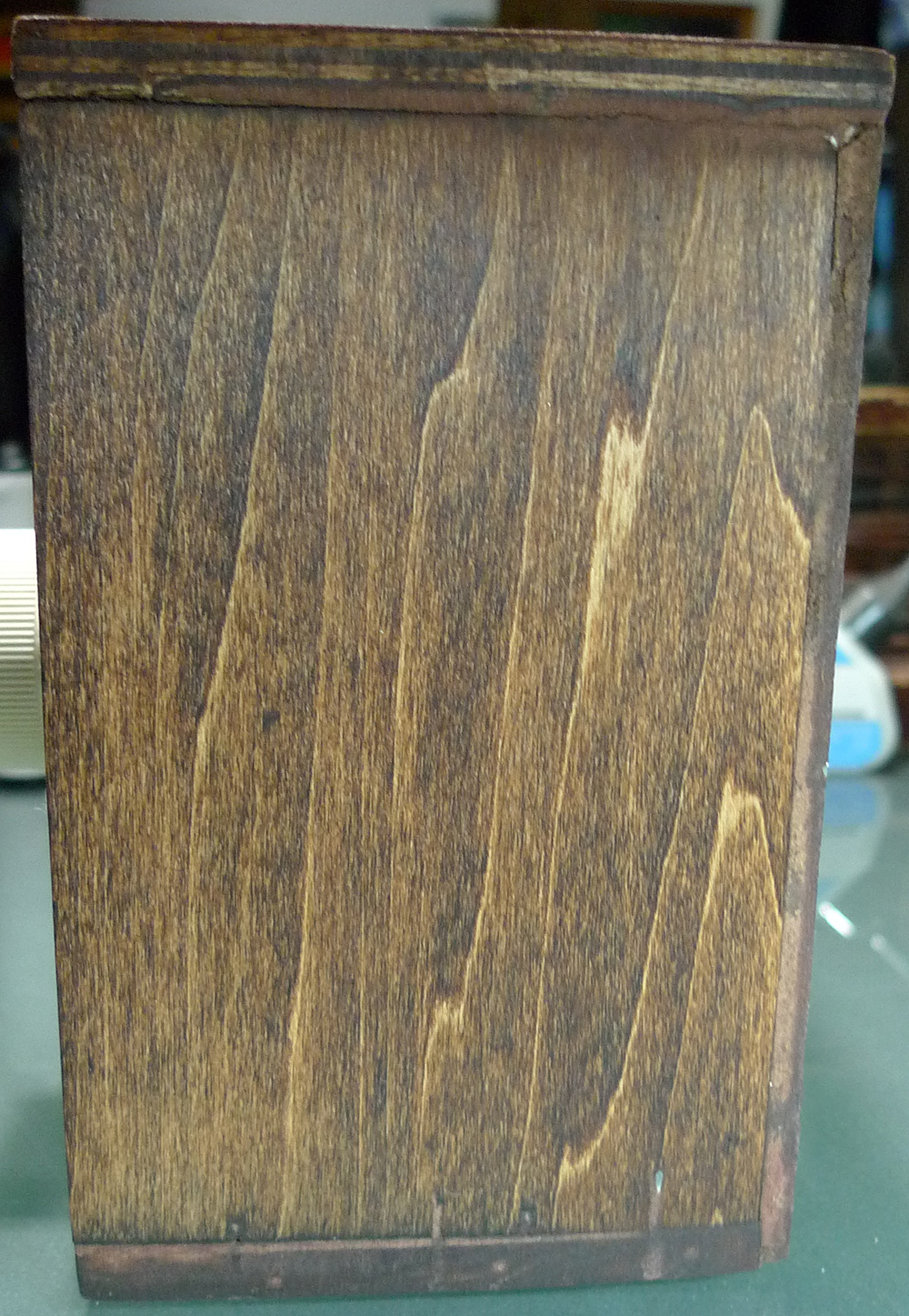
I boxed my contraption in with scrap wood that I had from previous projects. I stained it the other day which will help it blend in with stereo equipment.

Below shows a typical cable/wire layout to guide you as to which goes where in your system.
The longer cables/wires go TO your speakers.
The jumper cables/wires go TO your amplifier or receiver's speaker terminals.

I made these jumpers using banana plugs. With the wires passing through the terminals on the back side of the speaker plate, one should not push the bananas all the way in. You do NOT have to use banana plugs on your jumpers. Bare wires will work fine. You will insert them into the terminals on the front of the plate just as they are in the rear. Just make sure you are hooking Positive to Red and Negative to Black on each channel.
As I wrote, the jumper wires plug into your receiver or amplifier's speaker terminals. Left and Right, Positive and Negative. If your unit does not accept banana plugs, then the jumpers will have to be used bare.

As you can and have seen, I marked the terminal plate: L R and IN and OUT, then placed Scotch tape over the dried ink to prevent it from being rubbed off over time.
I prefer "twisted-pair" speaker cables. They reject radio frequency interference, including picking up the 50 or 60 Hertz AC hum from power cords and cables attached to your system.

Since I'm in the process of installing new cables on one of my receivers, I have marked them accordingly. These are the right channel's A and B cables.
Well, that is it! It may seem daunting, but you will have this device and like your digital meter, it will come in handy in the future.
Thanks for taking the time to read my humble blog. I really enjoy reading your comments and suggestions. This is a labor of love for me.
Scott
October 23, 2018
#281


