September 5, 2019
#326
Gentle reader,
Yesterday, I introduced you to our new $55 Channel Master 3016 TV antenna. You may read about it here:
Cord Cutting. Get TRUE HD Televison Via A Roof Mounted TV Antenna.
NOTE: To view the images larger, click on any one and a second window opens over this one. From that, you can click on each one or, use the < and > arrow keys to cycle through them.
My reasoning for taking it apart was two-fold, we recycle everything, and I wanted to examine it to see just how it worked. It is illegal to just throw away electronics. They must be disposed of properly.
As I wrote in the previous article, the old one, which was the second one we'd had, wasn't working very well. I'd bought an identical one even though the first one failed somehow. I did not learn from that failure and bought the same one. Which is the definition of.....

Back then, having never had an outside antenna, I wasn't aware of how electricity from the control box got to the antenna. As a result, I'd bought two fifty foot coaxial cables and situated the control box on top of a kitchen cabinet, with the cables coming and going through the kitchen ceiling even though the TV was in the living room. WAY too much cable and more work than needed.

These images are from Internet, advertising for this particular antenna. The one shown is an update for "4K". So the control box looks different and is a little larger.

Here you see it as it has been pulled from the box. Blue instead of light grey. Funny thing is, there are MANY different brands and variations of THIS antenna. And vastly different prices.

Walmart wants $65 for the blue LAVA model, but only $26 for this one under a different brand. The difference is semi-loops instead of half "X" blades hanging off the front.

On our much-used workbench is the subject, awaiting dissection. It is upside down. There are some damaged bits because I tossed it off the roof when I removed it, pole and all. Surprisingly little damage, actually.

Here is the top, it's "reflector" must have snapped off in a wind storm, which allowed rain to enter the unit. No telling when or where it landed.

The end that points towards the TV transmitter towers. And The, what I call, half X, pieces. Their job is to direct the signals to the top and bottom reflectors.

I bent the reflector back to show you the aluminum that is attached to the plastic cover. The protruding square piece houses the rotor motor.

And here it is, after removing the piece that is secured to the pole, mast is the correct name, and the covers.

The motor was off center to allow the whole unit to rotate centrally on the mast.

All the bits. The two metal pins on the box (above, left) are spring loaded and touch the bottom of a small circuit board inside, below.

You can see the color it was originally in the image above.

A jumper from inside the top at the rear where the two U shaped rods attached.
I had forgotten there were screws inside the corners and ended up prying the two halves apart, below. Oops.
Below, the corresponding attachment points for the U rods with wires soldered to the bottom of the circuit board.

The part with the X's on it has been removed, you can see the single screw inside the loop. The rod at the front is not electrically attached to anything.

The C shaped rod is the UHF element. The little circuit board above it is where the motor gets its electricity. The green stuff is glue.


I don't think it was reflecting very well any more.

Here are all the parts that had electricity or signals running through them.

A closer look at the signal preamplifier and motor control circuit board. I have seen over and over, that regardless where circuit boards are manufactured, they always have English lettering and numbers on them. For example, the "UF" of 220UF, is short for micro farad. Why a U? I don't know. Even the sticker, "QC" for quality control.

All of the pieces of aluminum that gather and catch the TV signals. The X pieces were actually in front of the C rod and small rod in the unit.

Compare those four pieces which are supposed to pull signals from 200 miles away to this one factually rated at 45 miles. Channel Master makes one rated at 100 miles but it is almost nine feet long!
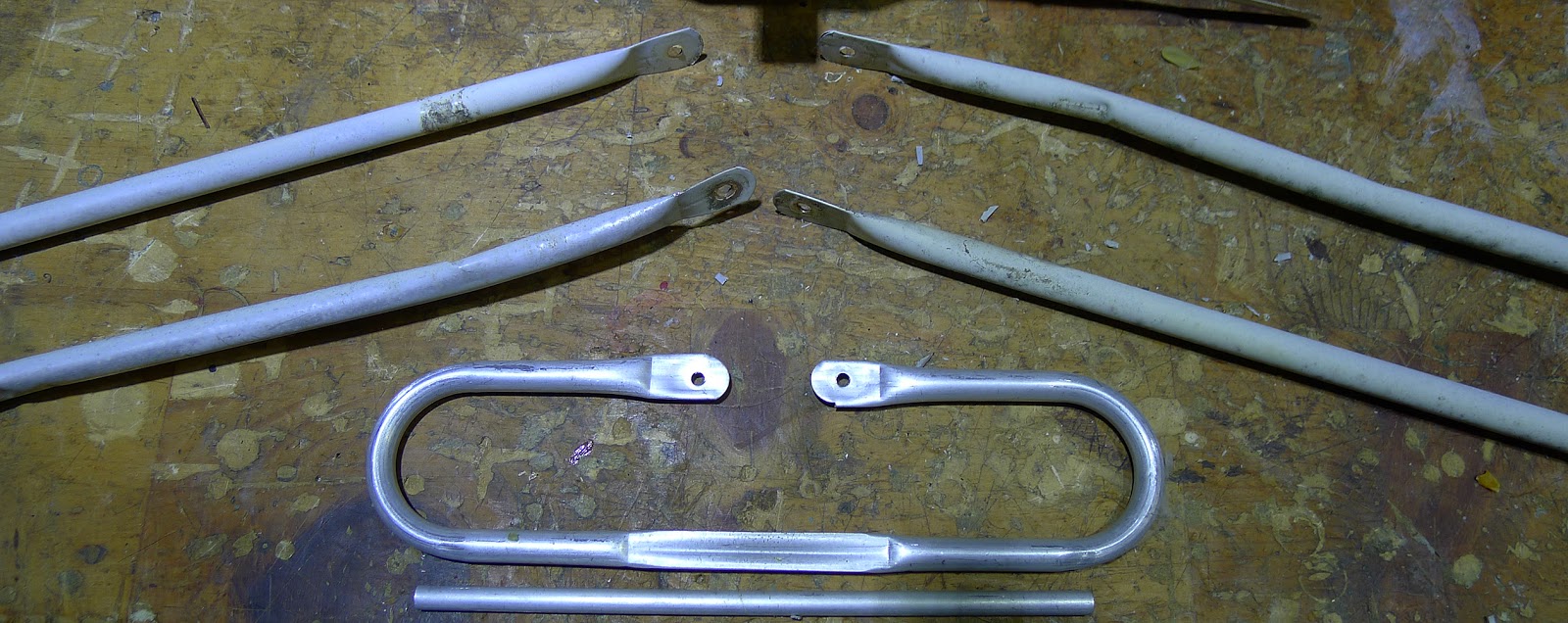
Three of these actually carried the signal to the circuit board. The little rod, I don't know it's purpose. But, they would not have put it there if it was not needed.

The half X assembly completely disassembled.

All the pieces ready for the recycling bin. The electronics are destined for the local hazardous waste collection facility.
Our county has a wonderful public-friendly landfill. It is setup in such a way that one backs their vehicle up to toss all their trash and debris into roll-off dumpsters. The tops are level with the area one drives and parks on.
There are collection receptacles for all kinds of recyclable items and the hazardous waste building is separate. You drive up, friendly people take all of our stuff and off you go.
Once again, I thank you for taking the time to read my humble blog. It is your kind words and comments that keep me writing them.
Scott
September 5, 2019
#326


No comments:
Post a Comment