September 10, 2020
#402
Gentle reader,
This article is third in a continuing series about creating or configuring a downhill 1/64th scale race course for diecast cars.
Previous episodes are linked below:
And the INDEX to EVERY article I have written about small cars:
For the uninitiated, ADULTS, mostly men, around the world are enjoying not only collecting "Hot Wheels" cars, but also racing them. In fact, more of these wee cars are sold to adults than kids by a large factor. Sadly, kids today are much more interested in interfacing with a device with a screen than playing and imagining in the real world. I blame the parents.
There are TWO YouTube channels that dominate this new phenomenon. 3DBotmaker is the most watched and emulated channel with Shri Lanka's DRC being second.
In 2020, 3D with the help of 2D built two new courses which make the previous year's course pale by comparison. They use a combination of their own 3D printed track pieces as well as Hot Wheels track and Crash Racers track. Watch their races, the 2019 and older aren't nearly as interesting, to see the phenomenal job they have done of creating two very life-like diorama/race venues and their commentating and banter is the icing on the cake.
The DRC in Shri Lanka has created two courses with almost everything hand made. This years "Yard Racing" and the earlier DRC course are quite something as are the races. Due to people around the world speaking many languages and watching his races, he uses a computer voice to announce and comment on the races.
NOTE: "HW" means Hot Wheels and "CR" means Crash Racers tracks.
NOTE: "HW" means Hot Wheels and "CR" means Crash Racers tracks.

You are likely thinking, "What am I looking at here?" And you are right to wonder.
Crash Racers (the grey track above) and Hot Wheels track (below) are very flexible by design. In the former, it has to flex to be able to attach to the high banked curves that make up their figure-8 (and now oval) circuits.

Hot Wheels track has to endure extreme curvature in order to be used in loops and hills and all the other ways it can be manipulated to have fun. These are classic HW track pieces that are two feet (24") long compared to the standard of one foot (12") of today. Plus, they have no holes in them.
In building a downhill race course (and uphill if running the Crash Racers or Hot Wheels K.I.T. electric powered cars) the track has to be stiffer and made to be fastened to the structure the builder creates to hold everything. One does not want to screw through the track pieces to hold them in place.
Hot Wheels created the standard dimensions for track design and joiners. Crash Racers and other companies have chosen to use the same "gauge" to connect their track pieces together.
The makers of Crash Racers could not have anticipated their figure-8 race kits being repurposed in the ways they have and are being done around the world by ADULTS.

These are "Super Jumbo" wooden craft sticks sold by Michael's and probably other craft stores.
They are actually wider than the spec. (below) and fit tightly into Crash Racers track. They are too wide to fit Hot Wheels track without distorting the track.

To connect Crash Racers track SECURELY, one needs something other than Hot Wheels track joiners. These craft sticks are as the old saying goes, "The cat's meow."
And yes, there are people who have created clever 3D printed joiners, but they are pricey.

Above is a super jumbo stick (top) next to a standard jumbo craft stick. The latter can be found here:
Amazon.com: 8 Inch Jumbo Wooden Craft Sticks (50 Pack): Arts, Crafts & Sewing
Amazon.com: 8 Inch Jumbo Wooden Craft Sticks (50 Pack): Arts, Crafts & Sewing

What I have done is use a combination of jumbo and super jumbo with standard 3/4" wide craft sticks as joiners to put them all together.

I used a miter saw by taping a stack of sticks together and cutting them "en mass" so they are equal length.

But I found later on, that using sturdy scissors to cut them singly will do the trick in a pinch.

Below are the three types/sizes of sticks as well as the underside of a piece of CR track.


The images above show why I cut off the rounded ends since they would form weak spots at the joints.

Now, if you look at this image and the ones below, they should make sense to you.

I used wood glue to bond them together, using a weight on a piece of wood on the top of the track in the case of the CR track and spring clamps with the HW track to increase the glue's adhesion. Regular Elmer's type white glue will also work as well as wood glue.

The Super Jumbo pieces are used on the end(s) of the CR track with standard Jumbo pieces in between.
I may redo these by cutting the 3/4" wide sticks so that there are no longer round ends and gaps between them for added strength. I have PLENTY of craft sticks to redo it.


As previously stated the Super Jumbo sticks are a bit too wide to fit the Hot Wheels track without distortion.
Carefully sanding the edges of them S-J sticks would narrow them enough to work as joiners and I may do that since the plastic HW joiners are quite flimsy by comparison.
All I would have to do is trace around a HW (classic) joiner onto the super jumbo craft sticks and use an electric sander to make them the correct width. You can see those orange HW joiners above and below.
All I would have to do is trace around a HW (classic) joiner onto the super jumbo craft sticks and use an electric sander to make them the correct width. You can see those orange HW joiners above and below.

We are using classic Hot Wheels track to avoid the BLUE DOTS which are every foot in most race courses seen on YouTube.


This image (above) shows the Jumbo craft sticks minus their round ends, in the top row, then the 3/4" wide pieces in place in the middle and one extra which covers the plastic joiner to complete the task.


The image above shows the spring clamps I use to press the glued sticks together until the glue sets. The track piece at the bottom is completed.
The image below shows a 1969 Hot Wheels Sizzlers Start/Brake piece with attached Chicane or esses track.
I have determined that the second set which we purchased (and seems to have never been used) might be better used right after the start gate OR possibly as a starting gate.
That way, the braking mechanism will not be needed to slow the cars before the chicane. Believe us, they HAVE to slow down or will go flying off the track.
 Above is a design study I did to try and create a course with lots of track to run on, but with limited floor space.
They are all stacked in the photo, but in OPPOSITE position, with the orange sections that would be on top, with a second dual-lane curve (which we now have) attaching to CR track.
Each CR section would be lower and lower with the final straight section (wooden joiners showing) ending somewhere to catch the speeding cars.
Think of a funnel (or funnel cloud) design with the widest section at the top and getting narrower as it goes downward.
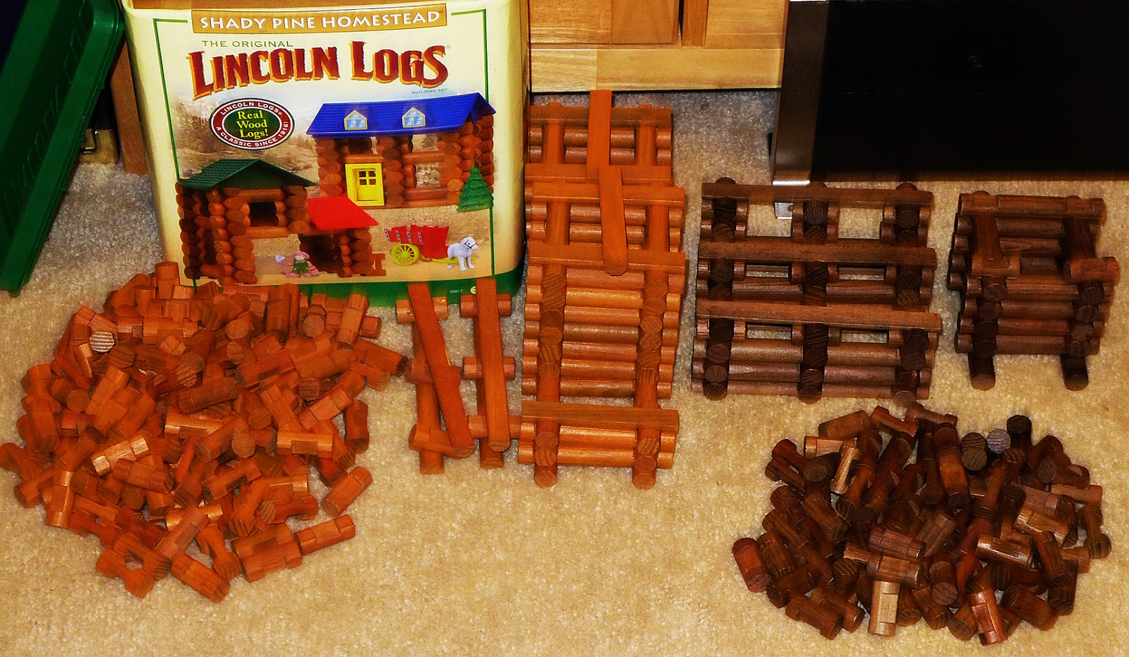
 Nancy found a bunch of Lincoln Logs at a thrift store which might be used in construction.
They can be glued together and to the craft sticks beneath to CR and HW tracks.
The track pieces could always be slid off the structure if needed.
 Here are all the Lincoln Logs we have at present. Whether we actually use them will be determined once we have come up with a final design.
Thank you SO much for taking the time to read our blog. Please take a moment to click the FOLLOW button, above and to the right, just below the end of the list of article dates.
Thank YOU to all of our followers. Also feel free to comment below or on Facebook.
Scott & Nancy
September 10, 2020
The image below shows a 1969 Hot Wheels Sizzlers Start/Brake piece with attached Chicane or esses track.
I have determined that the second set which we purchased (and seems to have never been used) might be better used right after the start gate OR possibly as a starting gate.
That way, the braking mechanism will not be needed to slow the cars before the chicane. Believe us, they HAVE to slow down or will go flying off the track.
They are all stacked in the photo, but in OPPOSITE position, with the orange sections that would be on top, with a second dual-lane curve (which we now have) attaching to CR track.
Each CR section would be lower and lower with the final straight section (wooden joiners showing) ending somewhere to catch the speeding cars.
Think of a funnel (or funnel cloud) design with the widest section at the top and getting narrower as it goes downward.

They can be glued together and to the craft sticks beneath to CR and HW tracks.
The track pieces could always be slid off the structure if needed.
Thank you SO much for taking the time to read our blog. Please take a moment to click the FOLLOW button, above and to the right, just below the end of the list of article dates.
Thank YOU to all of our followers. Also feel free to comment below or on Facebook.
Scott & Nancy
September 10, 2020


